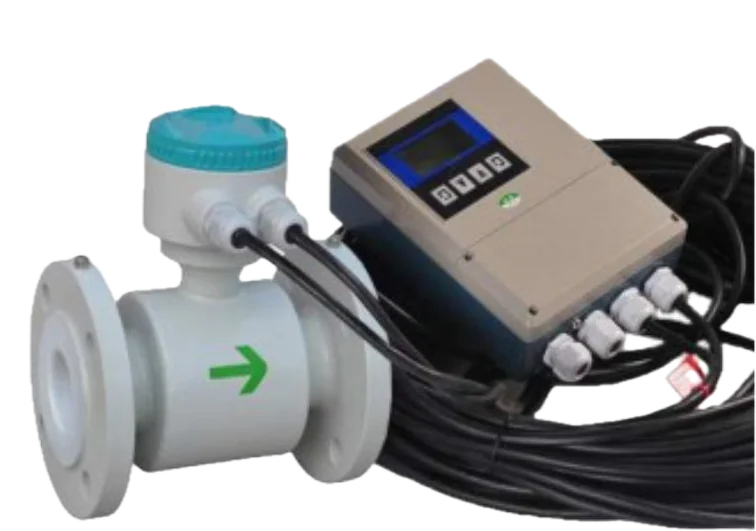
Full bore magnetic flow meter mechanical installation requirements install flow meter at low point of the system or with flow vertically up. Do not install at high point or with flow vertically down. On open drain lines with a drop of 5 metres or more install vacuum valve at high point.
Install in a U trap to ensure meter body is always completely full of liquid, allow 10 diameters of straight pipe before the meter & 5 diameters after to develop a smooth flow profile through the meter. More specific requirements are shown below.
Do not install close to pump inlet unless liner is suitable for vacuum operation, install meter 10D downstream of pump, or consider flow stabiliser. An upwardly sloping pipe is a good installation choice.
Preferred installation is with flow vertically up. This ensures the meter is always completely full of process fluid. This installation minimises wear of the liner by abrasive particles.
Horizontal flow is acceptable subject to the meter being kept full by an upstand in the downstream pipework. Horizontal applications require certain minimum straight lengths of pipe work before & after the flow meter.
In horizontal & sloping installations electrodes should be orientated so they are not at the top of the pipe. This will avoid entrained air or gases affecting the accuracy of the measurement.
When possible meters should be lifted with lifting lugs or shackles in the flange bolt holes. If this is not possible then soft slings should be wrapped around each end of the body to provide lifting points.
All flow meters which measure flow velocity perform best when the flowing fluid has a fully developed flow profile this generally occurs when the reynolds number is above 4500. Flow profile distortion & swirl can significantly degrade the accuracy & performance of all meters using this principle. These problems are often the results of practical requirements of the piping system such as, valves, tees, elbows etc. The full bore magnetic flowmeter is less susceptible to these adverse conditions than some other technologies. However the diagram above specifies the minimum straight lengths of piping that should be provided to allow the flow profile to stabilise after these typical flow disturbances. Whilst acknowledging the difficulties of achieving these straight length recommendations, particularly in large bore pipes, the less the compromises of the installation the better the performance of the meter will be.
This applies to the instrumentation aspect of the installation & addresses different issues to the safety grounding described below. Establishing a process ground is one of the most important installation details.
Proper process grounding ensures that the sensor and fluid are at the same potential so that only the induced flow signal is measured. The flow signal is connected to a differential amplifier that is electrically isolated from the case of the transmitter. The process of grounding provides a stable reference for this differential amplifier. In the majority of applications, the best and most stable reference is earth ground itself. By connecting the mag meter sensor, the fluid, and the reference for the amplifier to a stable, noise free reference point, the user is ensured of getting the best performance.
Ground rings are required when the piping adjacent to the mag meter does not provide a good electrical connection to the fluid. Ground electrodes are an integral part of the sensor, so installation is easier and less expensive, particularly when “exotic” materials are required. Ground rings provide a larger surface area of connection to the process fluid, and limit the effects of the conductivity of the adjacent piping, which is important for wafer style sensors. Therefore ground rings should be installed in the following situations:
To prevent hazards to operating personnel, electrical equipment must always be installed and wired as per local electrical code. For AC powered equipment, this usually takes the form of connection of the case of the equipment to earth ground. If the transmitter is integrally mounted to the sensor, this automatically connects the sensor to earth ground as well. It is common that the adjacent piping to the mag meter will provide a connection to earth ground. It is important that if both earth ground connections are established, the impedance between them must be very low. If the impedance between these earth ground connections is high, it can result in a high current through the coil shield wire.
When a flowmeter is installed and activated, its operations begin with a pair of charged magnetic coils. As energy passes through the coils, they produce a magnetic field that remains perpendicular to both the conductive fluid being measured and the axis of the electrodes taking measurements. The fluid moves along the longitudinal axis of the flowmeter, making any generated induced voltage perpendicular to the field and the fluid velocity. An increase in the flow rate of the conductive fluid will create a proportionate increase the voltage level. Because the coil position & spacing is constant the voltage induced is proportional to the volumetric flow rate. Because the voltage is small proper earthing is an essential requirement of the installation.
- Magnetic flow meter electrode selection
- Teflon (PTFE)
- The most chemically resistant material, resistant to hot hydrochloric acid & nitric acid as well as strong alkali & organic solutions
- Weak abrasion resistance
- Temperature rating up to 120°C
- PFA
- Similar abrasion & chemical resistance to PTFE
- More resistant to salt than PTFE, better for sea waterapplications
- Suitable for high pressure applications
- Merriman engineers can check chemical compatibility on request
- F46
- Suitable for high pressure & vacuum applications
- Temperature rating up to 160oC
- Neoprene
- Good resistance to abrasion
- Good elasticity & ductility
- Resistant to weak acids & alkalis, but avoid oxidizing chemicals such as sodium hypochlorite & ozone
- Use in water & sewage treatment, mineral processing such as low abrasive slurries
- Polyurethane
- Good abrasion resistance, use in abrasive slurries such as mineral processing &coal washeries
- Poor resistance to chemical & organic impurities
- A vacuum release valve fitted at the high point of a vertical drain line will allow it to drain after the pump has stopped
- A sloping pipe with an upward flow is also a recommended installation
- Adequate pipe support must be provided either side of the meter
- Straight pipe requirements
- Flow meter installation straight pipe requirements
- Grounding arrangements for general purpose magnetic flow meter
- Installations
- Magnetic flow meter process grounding
- Basic process grounding
- Magnetic flow meter grounding of signal amplifier reference
- Ground rings vs. Ground electrode
- The fluid conductivity is less than 100uS/cm
- Wafer style sensors installed in non-conductive piping or lined piping. Such as PVC & CPVC
- Applications that may cause a coating or build-up on the bottom of the pipe
- Electrolytic process or cathodic protection, these applications have special requirements contact sales@merrimancontrols.com for assistance
- Earth/Safety grounding
- Magnetic flow meter principle of operation